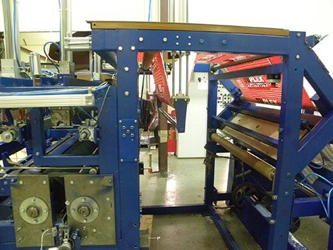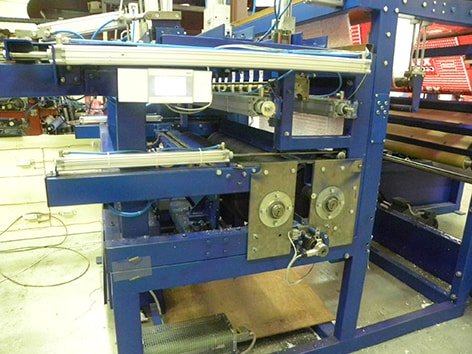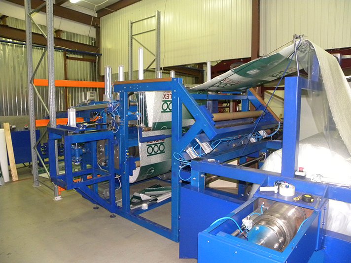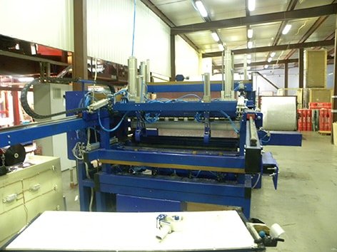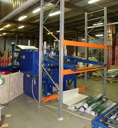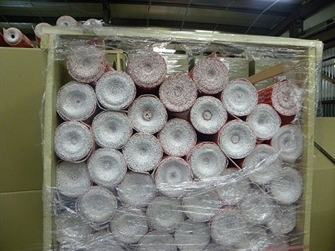
The automatic unit for rewinding, cutting to length, and rolling up material (hereinafter referred to as the “Unit”) is designed to perform the automatic process of rewinding, cutting to length, and rolling up material.
Technical specifications:
- Unit width, mm – 3700
- Unit length, mm – 5350
- Unit height, mm – 2100
- Unit weight, kg – 4000
- Input roll:
- weight, kg – 100
- diameter, mm – 1400
- Cut length (adjustable), m – 10
- Winding – Coreless roll
- Wound roll diameter, mm – 150–155
- Max. wound roll weight, kg – 2
- Drive – Electromechanical, pneumatic
- Type – Automatic
- Cutting blade – Mechanical
- Winding – Tight
- Roll unloading – Automatic
- Web threading – Manual
- Operator – 1 person
- Output, min. – 2 units/min
- Power supply – 380 V, 50 Hz
- Power consumption, kW – max. 10
- Pneumatic system pressure, atm – 6
Manufacturing utilizes top-quality, time-tested components from European manufacturers: pneumatic actuators and pneumatic control equipment from Germany (Festo), Lenze frequency converters and electric drives, and Siemens sensors and controllers.
Purpose:
The automatic unit for unwinding, cutting to length, and winding material into rolls (hereinafter referred to as the “Unit”) is designed to perform the automatic process of unwinding, cutting to length, and winding material into rolls.
The Unit consists of (see figure):
- Unwinding unit
- Rewinding and cutting unit
Job Description
A roll (100 kg) is transported by a forklift to the mounting position and clamped by cones engaging the core.
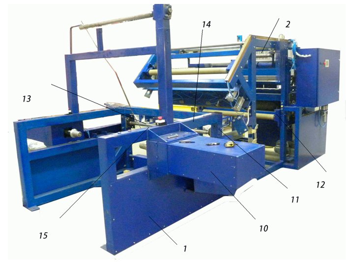
The cones (10) are driven; they handle both the unwinding and braking of the roll. An integrated system monitors torque and regulates material tension, as well as detecting material absence.
The material is pulled over a roller (11) equipped with a sensor that stops the process if defects (such as thickness irregularities) are detected. It is then fed into the feed rollers (12), passing between the clamping bars (13) and the end-splicing plate (14).
When the material runs out, the bars (13) press the material against the plate (14), and the suction cups (15) are activated. The material is drawn against the plate by the suction cups; the operator lowers the bar and trims off the defective end of the material.
Subsequently, after a new roll is installed, the leading edge is pulled under the lower clamping bar; once clamped, it is secured to the plate by the suction cups. By repositioning the bar, the operator trims the defective leading edge of the film to square off the end.
After trimming, the two ends of the material are taped together, and the machine resumes winding. Upon initial startup, the material—following the trimming of the leading edge—is inserted into the feed rollers (12). The feed rollers are controlled by a drive mechanism that automates the film feeding process.
A sensor positioned between the feed rollers monitors the material’s movement along the machine’s axis; if misalignment occurs, alignment cylinders adjust the material’s position.
An encoder mounted on one of the rollers measures the required length of material. The material is fed along guides through feed rollers, then passes between the winding shafts and enters the roll-forming zone.
The leading edge of the material strikes a deflector and is deflected onto a pressure roller rotating in the direction of material flow. Pushed by this roller, the material then encounters another roller that redirects the leading edge toward the winding shaft. A deflector strips the material from the winding shaft and directs it toward the incoming material, creating a loop. The loop-forming rollers are controlled by a separate pneumatic line with adjustable pressure, allowing for the regulation of clamping force. Once the loop is formed, the pressure rollers rise under the force of the incoming material. After an encoder registers the required length, a control signal is sent to stop all shafts. Pneumatic cylinders lift the pressure rollers to their uppermost position. An ejector moves the formed roll—which unwinds slightly during the process—onto the gripping arms. The material hold-down mechanism lowers, and a mechanical knife performs the cut. Following the cut, the control system reverses the shafts by 0.2 meters to return the edge to the loop-forming zone.
The cycle repeats.
After cutting, a mechanism activates to tuck the material edge (the offcut remnant). The roll is rotated into its final position and moved to the transport zone. A conveyor gripper assembly descends toward the roll with its grippers open. The conveyor grippers close, and the tucking mechanism releases the roll. The conveyor grippers then rise to the upper position. Cylinders responsible for transporting the roll activate; they are controlled by a valve capable of stopping the cylinder at any position, with the stop triggered by a reed switch signal. During transport, the conveyor gripper assumes a horizontal position. The conveyor grippers move along guide rails to their extreme position (beneath the sealing unit’s grippers) and “transfer” the roll to the sealer’s grippers.
The sealer’s grippers push the roll through the heat-shrink film (where the film sheets have been pre-sealed together). The pneumatic cylinders for the sealer’s longitudinal jaws actuate; the roll is sealed and cut from the film.
The label for the next roll is placed onto the sealed film.
The sealed roll rolls down toward the transverse sealing units. Following the transverse sealing operation, the roll is discharged onto the heat tunnel’s conveyor belt.
Advantages
- Automatic roll packaging with a throughput of at least 2 rolls per minute;
- Capacity to load multiple rolls into the accumulation tray;
- Adjustable conveyor speed;
- Modular design allows the line to be configured according to the customer’s requirements.
Description of the roll rewinder operator’s job
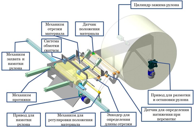
The material roll is positioned between the clamping cones and secured by the roll-clamping cylinder; the second cone is driven and serves to either unwind or brake the roll.
The material is pulled through a material position sensor, which monitors the web’s position and makes adjustments using cylinders.
It passes over the tension-sensing roller shaft, which synchronizes the operation of the unwinding and winding drives.
An encoder on one of the rollers measures the length of the cut material.
Knives cut the material to the required length.
Suction cups transfer the material from the knives to the feed cylinders.
Winding forks engage the tensioned material to wind it; once winding and cutting are complete, the roll is secured with adhesive tape rings. The roll is then gripped by cylinders (not shown in the diagram), the forks disengage, and the roll is transferred to the roll-sealing unit.
Additional information
12-month warranty
Post-warranty service